![]()
![]()
Administrator
Handbook
www.loriotpro.com
|
Administrator
Handbook |
TOC |
InterNetwork Map
LoriotPro displays a graphical presentation of your Network built at the IP level and based on the configuration of the discovered IP router. This view is called Internetwork Map and is automatically updated from any new Directory objects.
You can open the Internetwork Map window in many ways.
From the main menu select:
Supervise> Maps>Internetwork Map.
From the Map Tool Bar :
![]()
Click on icon: Internetwork
From the MinIMap:
Clicking once on the MinIMap displays the Internetwork Map centered on the selected zone.
Remark: If you double-click on a network object in the Internetwork Map window a new window is opened containing the hosts attached to this IP network. To return to the Internetwork Map, you must double-click on the network icon in the upper left corner.
The goal of the Internetwork map is to display all routers, networks and links between them. To display equipment and their status the software uses different icon types. The following table summarizes all these types and their meaning.
Remark: The Internetwork Map window uses three common objects: the host type, the router type, and the network type. These objects are displayed on a black background and texts are in black on a white background. All supervision functions can be applied to this three object types.
Table of icon associated background shapes
| Forms |
Examples |
Definitions |
| Square |
The host object icon The router object icon |
For a� host����� The device is displayed as a customized icon with a square as the background shape.� Its color changes when its status changes. For a router The device is displayed as a customized icon with a square as the background shape. Its color changes when its status changes. The status of a router is the same as the worst of any of its interfaces (hosts). � |
| Round |
The network object icon |
For a network The network is displayed as a customized icon with a circle as the background shape. Its color changes when its status changes. The status of a network is the same as the worst of any of its included hosts. |
LoriotPro tries to resolve the network technology from the information collected from SNMP and assigns a specific icon to them.
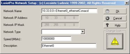
Remark: You can modify the automatically assigned icon by selecting the network type in the properties window of the network object or by loading an external icon.
Table of network icon types
| Icon types |
Network technology |
| |
Token Ring |
| |
Ethernet Example |
| |
Operator Network (cloud) (ISDN, RTC, X25, frame relay .) |
| |
Loopback |
| |
Point to point or leased line |
| |
Other network Example |
| |
It is possible to assign your own customized icon by choosing it in the network properties window |
The software offers you a choice of icon that represents routers. However, you can select your own customized icon.
Remark: An icons.ini file is located in the bin directory of the software and allows you to tailor the icon assignation of hosts and routers by the Discovery process.
Table of router icons
| Icon standard type |
Definitions |
| |
Router |
| |
Server, its main role is not to do routing |
| |
Switch with routing capabilities |
| |
Printer with routing capabilities |
| |
Firewall |
| |
It is possible to assign your own customized icon by choosing it in the router properties window |
Table of the status colors
| Colors |
Examples |
Definitions |
| Magenta |
A Host A router A Network |
The magenta color informs you that the object is not supervised For a host The device is not supervised and its exact status is unknown. For a router The device is not supervised and its exact status is unknown. For a network None of the devices in this network are supervised and their exact statuses are unknown. For a link The router interface with its associated IP address is not supervised. � |
| Blue |
A Host A router A Network |
The blue color informs you that the object answers to ping requests (ICMP hello packet). For a host The device is supervised with a periodic IP ping request but doesn't answer to any SNMP requests. For a router The set of the router's interfaces(host) or at least one of them are supervised by IP ping (ICMP hello packets). For a network����������� The hosts located in this network or at least one of them are supervised by IP ping (ICMP hello packets). For a link The router interface with its associated IP address is supervised by IP ping (ICMP hello packets). |
| Yellow |
A Host A router A Network |
The yellow color informs you that the object doesn't answer to SNMP requests but it could be a temporary condition For a host The device is supervised but doesn't currently answer to SNMP or ping requests For a router The set of the router's interfaces (host) or at least one of them are supervised but don't currently answer to SNMP or ping request For a network����������� The hosts located in this network or at least one of them are supervised but do not currently answer to SNMP or ping requests For a link ������ The router interface with its associated IP address is supervised but doesn't currently answer to SNMP or ping requests |
| Red |
A Host A router A Network |
The red color informs you that the object doesn't answer to SNMP requests and is probably down or out of order. For a host The device is supervised but has not been answering SNMP or ping requests for a while. For a router The set of the router's interfaces (host) or at least one of them are supervised but have not been answering SNMP or ping requests for a while. For a network����������� �The hosts located in this network or at least one of them are supervised but have not been answering SNMP or ping requests for a while For a link ������ The router interface with its associated IP address is supervised but hasn't been answering SNMP or ping requests for a while |
The status colors of the hosts located in a network define the color assigned to the network icon in the map.
The priority in color assignment is as follows:
Red > Yellow > Blue > Magenta.
Example :
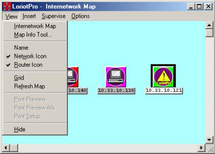
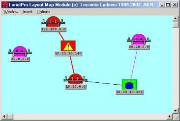
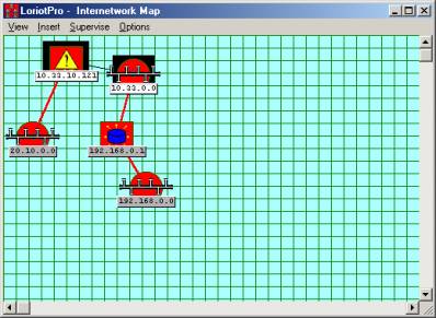
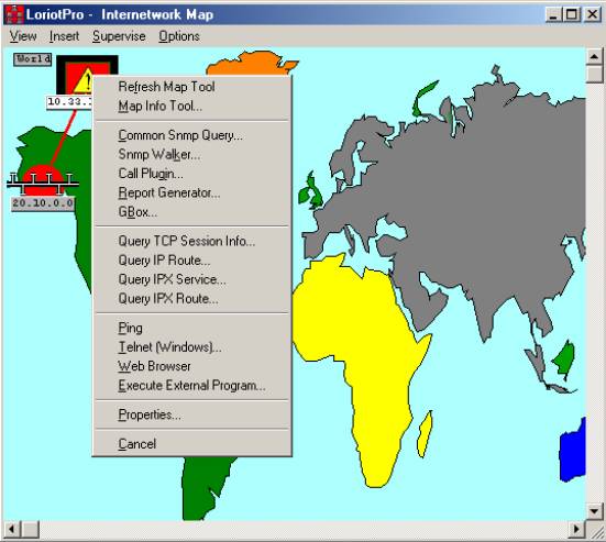
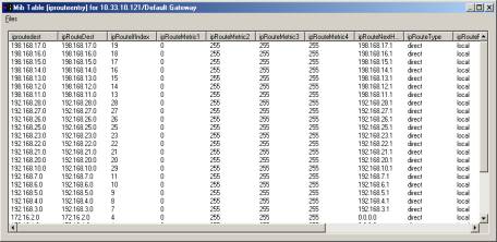
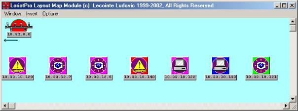
In the screen capture below, the 10.33.10.140 host has a red status and the network icon 10.33.0.0 is also red in the map.
Also, the 10.33.10.140 host is an interface of the 10.33.10.140 router ID, so the router icon inherits a red status.
The link between the 10.33.10.140 router ID and the 10.33.0.0 network is red because the 10.33.10.140 interface is defective and in red status.
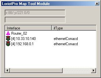
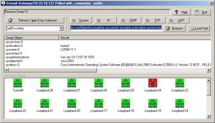
 The host objects of the 10.33.0.0
network and their color-defined statuses .
The host objects of the 10.33.0.0
network and their color-defined statuses .

A topological view with objects and their statuses
The Internetwork Map associated tools are numerous most of which have already been seen in the previous chapter.
The window has a menu bar and context menus associated with the icon type.
View Menu
The table under the screen capture below describes the various options of the view menu.
Table of the view menu option
| Options |
Descriptions |
| |
This option displays the topological map. |
| |
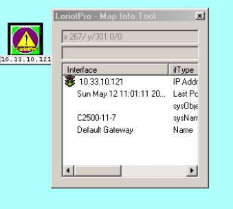
This option shows a modal window displaying real-time information about devices. If you place a pointing device over an object, information is automatically displayed in this window. |
| |
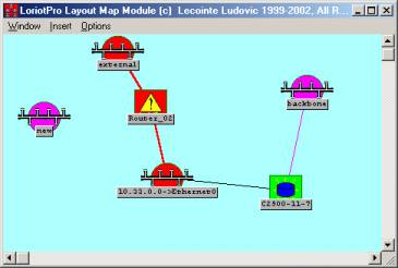
By default, IP addresses are used to name devices on the map. However, it is possible to assign mnemonic names to them. The default With names |
| |
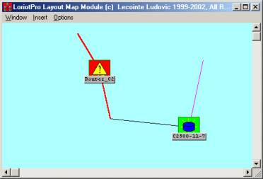
Toggle Network icon display |
| |
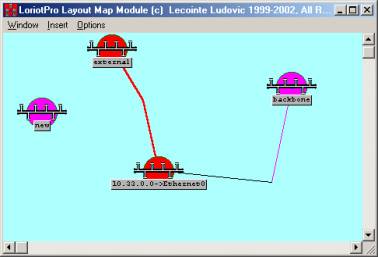
Toggle router icon display |
| |
Toggle grid display |
| |
The map is automatically refreshed at regular intervals, this option performs an immediate refresh.�� |
| |
This option hides the Internetwork Map |
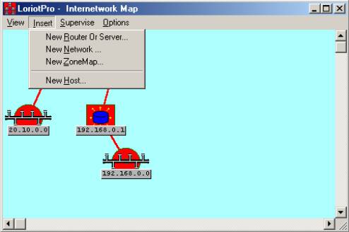
The table under the screen capture below describes the various options of the Insert menu.
Table of options of the Insert menu
| Options |
Descriptions |
| |
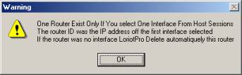
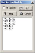
This option inserts a router in the map from the unassigned directory hosts Example Remark: In the chapter on router insertion more explanations are given. It is better and easier to use the context menu to insert a router directly at� the right location in the map.� |
| |
This option inserts a network in the map. Example Remark: In the chapter on network insertion more explanations are given. It is better and easier to use the context menu to insert a network directly at the right location in the map.���
|
| |
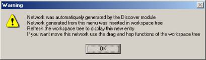
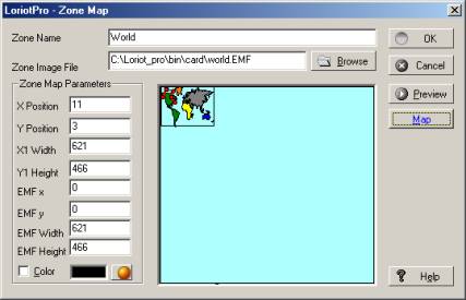
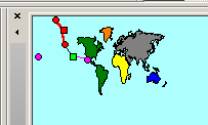
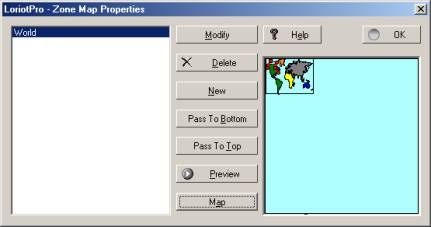
This option allows you to insert a Zone map from an image file (EMF format) to have a background of your choosing. The surface used by the image is called ZoneMap. It is better and easier to use the context menu to insert a Zonemap directly at� the right location in the map.��� Remark: This ZoneMap will be indexed by the Map Tool Bar and therefore can be directly selected. LoriotPro uses EMF (Extended Meta File) as ZoneMap images. |
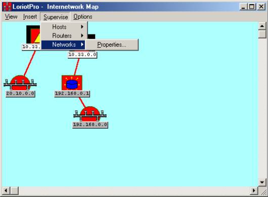
The supervise menu contains all options needed to supervise and administrate devices. It is divided into three sub-menus for each type of object.
To supervise an object, select it either in the Directory or in the map, and a black background should display confirming the selection. All options selected in the menu will be applied to the selected object.
Options available in the supervise menu are the same as those described in the main menu.

Supervise>Host
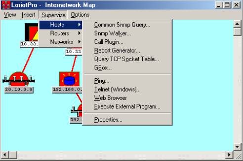
Supervise>Routers

Supervise>Networks
The options menu contains various commands used to manage graphical interfaces and window properties.
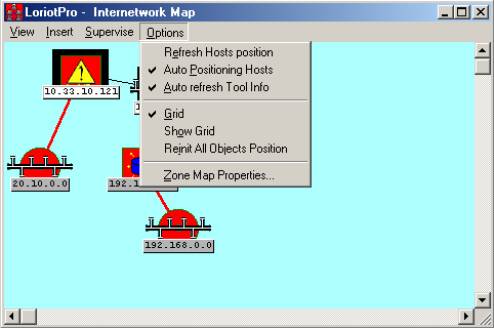
Table of the Options menu
| Options |
Descriptions |
| |
This option refreshes the host position in the network window. |
| |
Hosts are automatically set in network Map. |
| |
The Tool Info window is refreshed when the mouse is moved. |
| |
Uses the grid. |
| |
Toggles the grid display |
| |
The software, by default, sets the object on the map but this is not necessarily the object's real location. Later on, you can arrange the map by moving icons where you want by simply using the drag-and-drop function. This command destroys all your settings and reorganizes the objects' locations. Remark: The algorithm used is CPU time consumption and should be cautiously started on a small internetwork only (50-150 routers/networks). It is possible to manually locate the router on the map and to let LoriotPro locate the network objects. |
| |
It is possible to modify the Zonemap object parameters. |
If you right click on an empty area of the map the global context menu appears.
Remark: This is the same menu as the insert menu seen previously. The only difference is the capability to insert a new device object or a Zone map where the menu has been called. This is the fastest and easiest way of object creation.
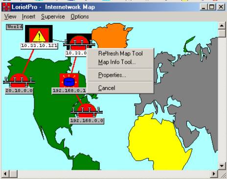
If you right-click when a router object is selected on the map you access the Router context menu.
Remark: This menu's options are described in the next chapter
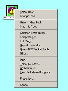
Table of Router context menu options
| Options | |
|---|---|
| |
Refresh the displayed information of the Tool Map window.� |
| |
Open the Tool Map window |
| |
Open the common SNMP queries window. |
| |
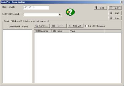
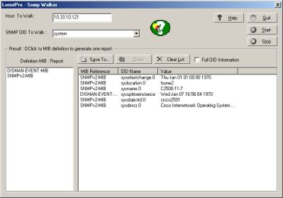
Open the Snmp walker window. |
| |
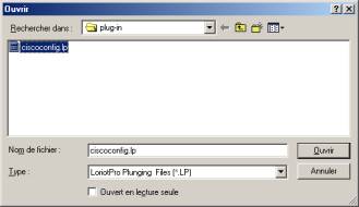
Allows you to attach a plug-in to the router reference IP address. |
| |
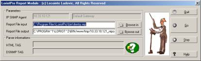
Start the report generator engine with the router reference IP address. Remark The Report Generator tool is explained in the next chapter. |
| |
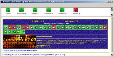
Start the Gbox tool with the router reference IP address. |
| |
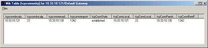
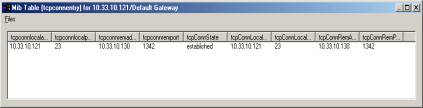
Shows the� router TCP active sessions� window. |
| |
Display the router IP routing table. |
| |
Displays the router Novell SAP table.
|
| |
Displays the router Novell IPX routing table.
|
| |
Start the Windows Ping tool with the router reference IP address. |
| |
Start the Windows Telnet tool with the router reference IP address. |
| |
Start your preferred Web navigator with the router reference IP address as URL (http://ip_address/ |
| |
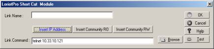
Start any external program with the router reference IP address as line parameter. |
| |
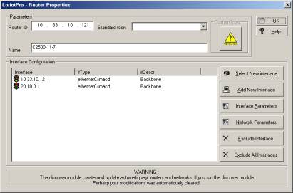
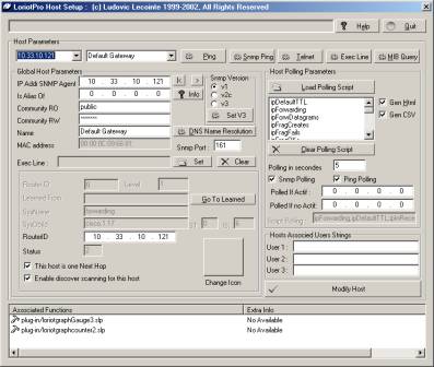
Open the router properties window Remark: The details of this window will be seen in a subsequent chapter � |
| |
Quit the menu |
Network context Menu
If you right-click when a network object is selected on the map you access the Network context menu.
Remark: These options are described in subsequent chapters.
Table of options found in the Network context menu
| Options | Descriptions |
|---|---|
| |
Refresh the displayed information of the Tool Map window.� |
| |
Open the Tool Map window |
| |
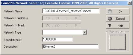
Open the Network properties window Remark: Details on this window are given in subsequent chapters |
| |
Quit the menu |
If you right-click when a host object is selected on the map you access the Host context menu.
Remark : These options are described in subsequent chapters.
Table of options found in the Network context menu
| Options | Description |
|---|---|
| |
The selected host becomes the default host. All subsequent commands will be applied to it . Remark: To select a host, simply left click on it. |
| |
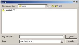
This option allows you to change the host icon. |
| |
Refresh the Tool Map window information. |
| |
Open the Tool Map window. |
| |
Open the Common Query window. |
| |
Open the Snmp Walker tool window. This tool discovers the MIB objects that a device implements. |
| |
This option allows you to attach a plug-in task to the selected host. |
| |
Start the report generator engine with the host IP address. Remark: The Report Generator tool is explained in a subsequent chapter. |
| |
Display the host TCP active sessions. |
| |
Open the Gbox that displays a graphical view of the host interfaces. |
| |
Start the Windows Ping tool with the router reference IP address. |
| |
Start the Windows Telnet tool with the router reference IP address. |
| |
Start your preferred Web navigator with the router reference IP address as URL (http://ip_address/) |
| |
This option allows you to start an external program with host parameters in the command line. |
| |
Open the host advanced properties window. Remark: Details on the options found in this menu will be seen in subsequent chapters. |
| |
Quit the menu |
|